JK BMS and solar inverters: common CAN/RS485 communication problems and how to check them
The cable fits, the battery works – and the inverter still reports a BMS error. A practical checklist for finding out why a JK BMS and a solar inverter will not talk to each other.
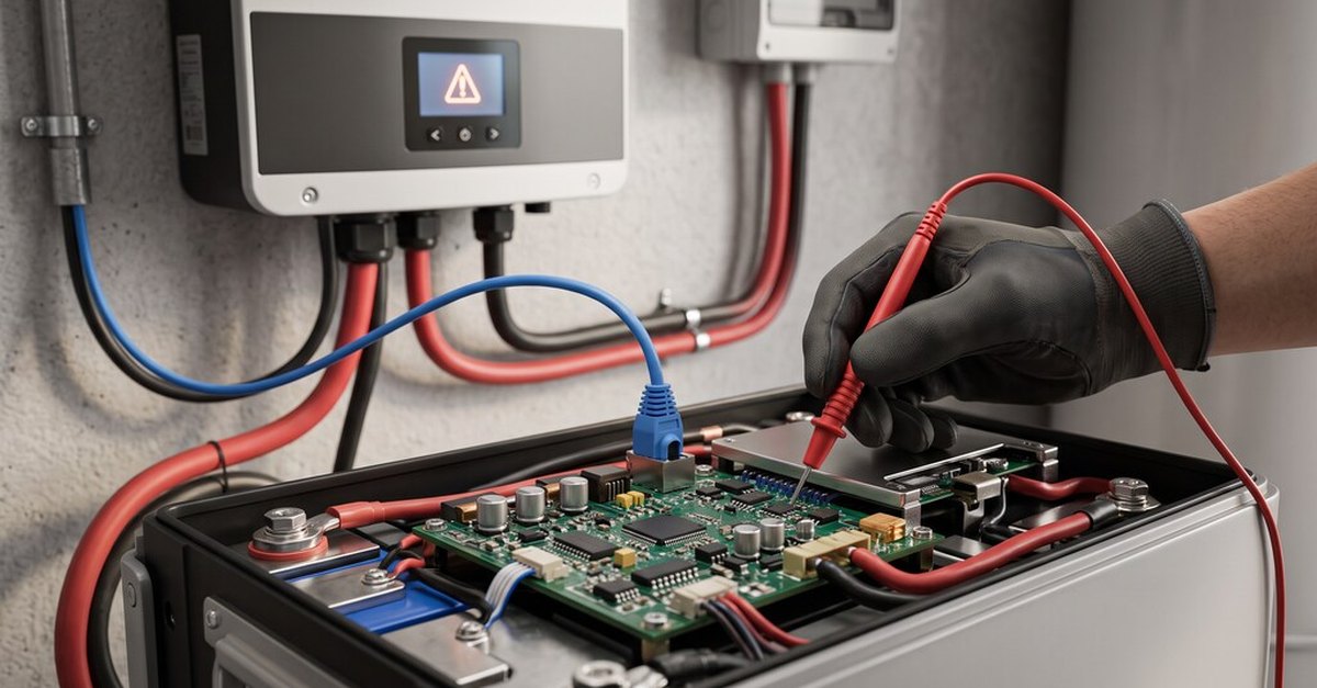
Connecting a JK battery management system (BMS) to a solar inverter should be straightforward. Both devices may have CAN or RS485 ports, the right-looking cable is connected and the battery itself works normally. Yet the inverter still reports a communication error, shows no battery information or refuses to recognise the BMS.
These problems are common in DIY LiFePO4 battery systems. The difficulty is that communication compatibility involves more than having the same physical interface. Before replacing the BMS or changing inverter settings at random, it helps to understand what can actually prevent two devices from communicating.
Having CAN or RS485 does not guarantee compatibility
A common misunderstanding is that any BMS with a CAN port will communicate with any inverter that also supports CAN. CAN and RS485 describe communication interfaces; they do not define all the data the devices exchange. For communication to work, the BMS and inverter must agree on:
- the interface: CAN or RS485
- the supported protocol and message format
- the communication speed and related settings
- the cable pin assignments
- device addressing, where required
- the battery information and control messages the inverter expects
An inverter may, for example, expect battery data in a Pylontech-compatible CAN protocol while the BMS is set to a different one. Even with correct wiring, the inverter will not recognise the messages. The first rule is simple: match the protocol, not just the connector.
The inverter cannot detect the BMS
A typical symptom is a BMS communication fault on the inverter, or no battery information at all, although the battery is switched on. Start with the physical connection.
Check the cable. An RJ45 connector does not mean a standard Ethernet patch cable will work. Different BMS and inverter models assign CAN_H, CAN_L, RS485_A and RS485_B to different pins, so compare the pinout diagrams in both manuals before connecting. For CAN, CAN_H must go to CAN_H and CAN_L to CAN_L; for RS485, check the A and B assignments against each manufacturer's definitions, which are not always labelled consistently. Do not rely on cable colour or connector appearance.
Check the port. Some JK BMS models have separate ports for inverter communication, PC monitoring and battery-to-battery communication. They may look alike but serve different purposes. Check the exact BMS model and interface-board documentation, and make sure the BMS is powered and operating normally – a correctly wired cable cannot connect to an inactive interface.
Correct wiring, but still no communication
If the cable is right, check the selected protocol. Many JK inverter BMS models offer several CAN and RS485 protocol options, including profiles for different inverter families, but the available profiles depend on the BMS model and firmware. A profile listed in the configuration app does not mean compatibility with every inverter carrying that brand name.
On the inverter, look for the battery communication settings – depending on the model they may be called lithium battery communication, battery protocol, BMS communication, CAN/RS485 battery mode or battery manufacturer profile. Compare the selection with the profile required by the JK documentation; choosing the wrong one can cause errors even with a correct electrical connection.
On the BMS, open the JK configuration app and check which protocol is selected for the inverter interface. Use the documented profile for your specific inverter model, and check that the BMS firmware supports the protocol version the inverter manufacturer requires. Record the original settings before changing anything.
CAN speeds do not match
CAN devices must run at compatible bit rates, and not every CAN network uses the same speed. Some JK inverter BMS documentation lists 250 kbit/s as the default CAN speed, while other protocol configurations and inverter integrations use 500 kbit/s – it depends on the exact hardware, firmware and protocol.
Victron systems show why this matters: in documented Victron GX installations, BMS-Can communication commonly runs at 500 kbit/s, while VE.Can networks may use 250 kbit/s. Both use CAN, but they are not interchangeable. A speed mismatch can block communication even when the cable and protocol are right.
What to check:
- the CAN bit rate required by the inverter
- the bit rate used by the selected JK BMS protocol
- whether these settings can be changed
- that the correct CAN port and network configuration are used
- restart or reinitialise the connection only as the manuals describe
Changing the bit rate alone will not fix the problem if the protocol and messages do not match.
The inverter shows voltage but no SOC
Sometimes the inverter shows a plausible battery voltage, but the state of charge (SOC) is missing, wrong or not updating. Seeing the voltage does not prove BMS communication: the inverter can measure voltage at its DC terminals independently of the data link.
Depending on the protocol, a working link should give the inverter the battery voltage and current, SOC, temperature, charge and discharge current limits, and warning and protection states. If only the voltage is visible, check whether the inverter has actually recognised the BMS, then compare the SOC in the JK app with the inverter's value:
- If the JK app itself shows an unexpected SOC, investigate the BMS configuration, current measurement and SOC estimation.
- If the BMS reports a sensible SOC but the inverter shows something else, look at protocol selection, data interpretation and link stability.
An SOC discrepancy is not automatically a wiring fault – SOC estimation errors can also come from inside the BMS.
Communication works, then drops out
Intermittent faults are harder to diagnose than a complete failure. Possible causes include poor connections, wrong bus termination, electrical interference, unstable device power or configuration problems.
Physical connection: make sure connectors are fully seated and cables are not damaged or strained. Avoid running low-voltage communication cables alongside high-current battery or AC conductors, and use the cable type, shielding and grounding the manufacturers recommend.
CAN termination: CAN networks usually need termination at both physical ends of the bus – in a conventional high-speed CAN layout, typically 120 ohms at each end. Some devices have internal termination resistors or use specific layouts, so adding extra resistors without checking can create a new problem. Follow the manufacturer's wiring diagram.
Firmware and operating conditions: record the firmware versions of both devices, review error and event logs where available, and note whether the failure happens at start-up, at high charging current or during a battery protection event. A shutdown caused by battery protection is not a communication fault.
Several battery packs do not communicate correctly
Parallel installations add requirements: a designated master BMS, unique communication addresses and a supported battery-to-battery link. The inverter may talk only to the master unit; the exact architecture depends on the JK model and system design. Common mistakes are duplicate addresses, wrong battery-to-battery wiring, using a port meant for something else, and assuming that if one battery works, several will too.
Before adding packs, check whether the BMS supports the planned parallel configuration, the master/slave or addressing settings, the inter-battery connections, the maximum number of units and the inverter communication arrangement. Communication is only one part of a safe parallel system – voltage matching, current sharing, cable sizing and protective devices matter just as much.
A practical troubleshooting checklist
Working systematically is more effective than changing several settings at once.
| Step | What to check | Why it matters |
|---|---|---|
| 1 | Exact BMS and inverter models | Different models may use different hardware and protocols |
| 2 | BMS operating condition | The device must be powered and not in an unexpected protection state |
| 3 | CAN or RS485 selection | Both devices must use the intended interface |
| 4 | Cable pinout | Similar connectors may have different signal assignments |
| 5 | Communication protocol | Both devices must support compatible message formats |
| 6 | Communication speed | An incompatible bit rate can block CAN communication |
| 7 | Firmware versions | Available protocols and settings may vary |
| 8 | Termination and wiring | Incorrect bus wiring causes unreliable communication |
| 9 | Battery addressing | Especially important in multi-battery systems |
| 10 | Live battery data | Verify SOC, voltage, current limits and alarms |
The order matters: first the hardware and connection, then the communication settings, and finally whether the inverter receives and uses the battery data correctly. Changing several parameters at once may clear an error temporarily but hides the original cause. For systems still being specified, AmpBird has published a JK BMS inverter compatibility and CAN/RS485 checklist covering protocol selection, wiring and pre-purchase checks.
What to verify before buying a JK BMS
Communication troubleshooting is easiest before the equipment is bought. Confirm with the supplier:
- Battery: chemistry (e.g. LiFePO4), number of cells in series, continuous and peak current, operating voltage range
- Inverter: exact model, battery voltage requirements, supported CAN/RS485 protocols, connector and pinout, firmware version where relevant
- BMS: exact JK model and hardware revision, supported inverter profiles, firmware and configuration options, cable requirements, parallel communication support if needed
A 16S LiFePO4 battery, for example, has a nominal voltage of 51.2 V, but its operating voltage varies, so the BMS must suit both the electrical and the communication requirements. A compatible protocol cannot make up for an undersized BMS or an unsuitable voltage range – and a higher current rating does not guarantee communication compatibility. These are separate checks, and both are needed.
The bottom line: most JK BMS communication problems come down to three areas – the physical connection, the selected protocol and the device configuration. Verify model numbers, pinouts and profiles before replacing hardware, and treat supplier compatibility lists as a starting point for checking, not a guarantee.